
Introduction
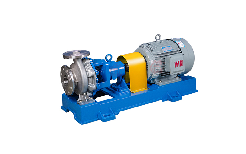
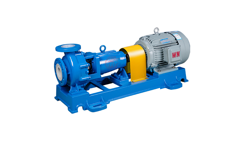
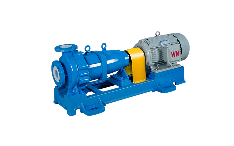
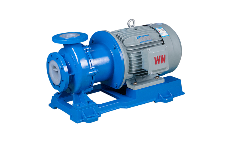
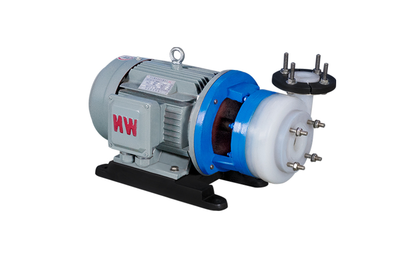
Suitable for pickling and painting process in automobile manufacturing; Electrolytes in nonferrous metal smelting; Ionic membrane caustic soda project is the largest ammonia, waste water treatment and acid adding process. According to the international design, the flow parts are all tightly lined with fluorine material, and the bearing part of the pump is metal material. Equipped with external bellows mechanical seal, easy installation and easy maintenance.

Advantage
Equipped with external metal bellows mechanical seal, grinding material: alumina VS tetrafluoroides, silicon carbide VS tetrafluoroides, cemented carbide VS cemented carbide, grinding can be selected according to working conditions.
Product breakdown chart

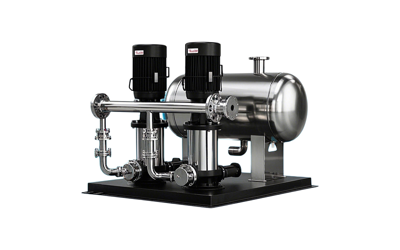
Factory photo display

Pump installation sequence
(1) When the unit is transported to the site, the pump and motor have been corrected by the person with the base, and the pump and motor need not be removed when leveling the base, so the installation is very convenient;
(2) Place the base on the foundation, and pad the wedge iron near the anchor screw, and pad the base 20~ 40mm high for leveling and filling with cement slurry;
(3) Check the levelness of the base with a level, fill the base with mud after leveling, and check the levelness again after the cement dries;
(4) When the power of the unit is large, in order to facilitate transportation, the pump, motor and base may be packaged separately, which requires the user to install themselves;
The method of correcting the pump unit is as follows:
(1) Clean the dirt on the supporting plane of the base, the pump foot and the motor foot plane, and put the pump and the motor on the base;
(2) Adjust the level of the pump shaft, and fix the pump on the base with bolts after leveling to prevent walking;
(3) Lift the motor, make the pump coupling and motor coupling match, put down the motor on the base of the corresponding position;
(4) Adjust the gap between the two couplings to about 5mm, and correct the shaft line of the motor shaft and the pump shaft to coincide, the method is to put the square on the coupling, the two couplings should be flat with the square, if not coincide, should adjust the relative position of the motor or pump, or the pad with thin iron to adjust;
(5) In order to check the installation accuracy, to measure the gap between the two coupling planes in several different positions on the circumference of the coupling, the difference between the maximum and minimum gap on the coupling plane one week shall not exceed 0.3mm, and the difference between the two ends of the center line or around shall not exceed 0.1mm.
(6) When the unit does not have a base, it needs to be installed directly on the basis, the method is similar to 4, but should pay more attention to correction.
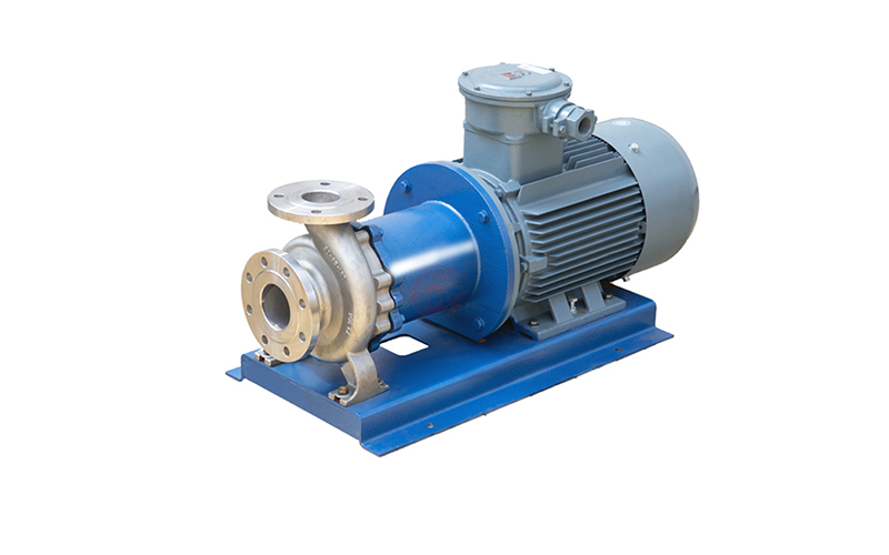
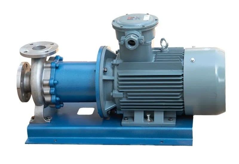
The causes and solutions of heating and vibration in fluorine lined magnetic pumps
Fluorine lined magnetic pumps perform well in handling corrosive media, however, some users may encounter issues such as heating and vibration during use.
When using fluorine lined magnetic pumps, different operating environments and usage conditions may lead to different problems. We first need to understand the possible causes of heat and vibration in order to address these challenges in a targeted manner.
Reasons for heating and vibration:
1. Changes in fluid characteristics: Changes in fluid viscosity may cause pump heating. The viscosity of a fluid is not only affected by temperature, but may also fluctuate due to changes in the properties of the fluid itself.
2. Pump misalignment or damage: If the internal components of the pump are misaligned or damaged, it may cause abnormal vibration during operation, leading to heating.
3. Abnormal system pressure: Excessive or insufficient system pressure may affect the normal operation of the pump, causing heating and vibration of the pump body.
Solution:
1. Fluid characteristic matching: Ensure that the selected fluid matches the design parameters of the pump, regularly monitor changes in fluid properties, adjust operating parameters to reduce problems caused by changes in fluid characteristics.
2. Regular maintenance and inspection: Implement a regular maintenance plan to inspect the internal components of the pump to ensure they are not misaligned, damaged, or worn. Defective components should be replaced promptly.
3. Accurate alignment of pump body: Ensure correct installation and alignment of the pump. Incorrect alignment may cause uneven force on the pump during operation, leading to vibration and heating.
4. System pressure control: Regularly monitor and control the pressure of the system to ensure operation within the pump design range. Avoid high or low system pressure.
By adopting the above solution, users can expect to improve the reliability of fluorine lined magnetic pumps, reduce maintenance costs, extend equipment life, and ensure the smooth operation of fluid conveying systems.
It is crucial to have a deep understanding of the causes of heating and vibration in fluorine lined magnetic pumps, and to adopt corresponding solutions to ensure the long-term stable operation of the pump and the reliability of the system. Through reasonable operation and maintenance, users can better utilize the advantages of fluorine lined magnetic pumps to meet actual production needs.
How to improve the anti cavitation performance of centrifugal pumps
1、 Measures to improve the effective cavitation margin of the liquid inlet device:
(1) Change the suction device to a backflow device.
(2) Reduce the installation height of the suction device pump.
(3) Increase the pressure of the liquid level in the storage tank in front of the pump to increase the effective cavitation margin.
(4) Reduce the flow loss in the pipeline before the pump. Try to shorten the pipeline within the required range, reduce the flow rate in the pipeline, reduce bends and valves, and increase valve opening as much as possible.
2、 Measures to improve the anti cavitation performance of centrifugal pumps themselves:
(1) Improve the structural design of the pump from the suction port to the vicinity of the impeller. Increase the overcurrent area; Increase the curvature radius of the inlet section of the impeller cover plate to reduce the rapid acceleration and pressure drop of the liquid flow; Properly reducing the thickness of the blade inlet and rounding the blade inlet to approach a streamline shape can also reduce the acceleration and pressure drop around the blade head; Improve the surface smoothness of the impeller and blade inlet to reduce resistance loss; Extend the inlet edge of the blade towards the inlet of the impeller to allow the liquid flow to receive work in advance and increase pressure.
(2) By using a double suction impeller, the liquid flow enters the impeller from both sides simultaneously, doubling the inlet cross-section and reducing the inlet flow rate by one.
(3) By using a pre induced wheel, the liquid flow performs work in advance in the pre induced wheel to increase the liquid flow pressure.
(4) Using anti cavitation materials. Practice has shown that the higher the strength, hardness, and toughness of materials, the better their chemical stability, and the stronger their resistance to cavitation.
(5) The design condition adopts a slightly larger positive angle of attack to increase the blade inlet angle, reduce the bending at the blade inlet, reduce blade blockage, and increase the inlet area; Improve working conditions under high flow rates to reduce flow losses. But the positive angle of attack should not be too large, otherwise it will affect efficiency.
The above measures can be comprehensively analyzed and applied appropriately based on the selection of pump types, materials, and on-site usage conditions.