

Introduce
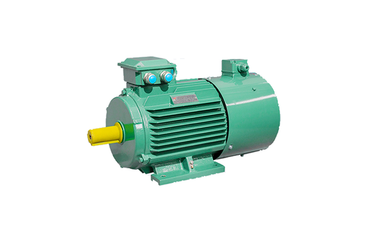
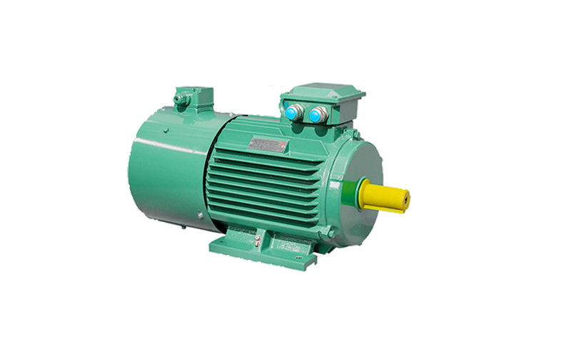
Y2VP series variable frequency speed regulating low voltage
Frame number: H80-450
Capacity: 0.55~900kW
Voltage: 1140v and below
Frequency range: 5~100Hz
What kind of oil does the motor of the pump need to be lubricated with
The lubrication of the pump motor usually uses a specific electric oil or grease. Choosing the right lubricant depends on the type of motor, operating conditions and manufacturer’s recommendations. Here are some common options:
Electric oil: For enclosed motors that require oil lubrication, special electric oil is usually used. This oil is usually transparent and has good insulating properties and thermal stability.
Grease: For bearings and other moving parts, grease is usually used. The grease forms a protective film over the lubricated area, reducing wear and preventing corrosion.
Multi-purpose greases: For less demanding environments, multi-purpose greases can be used, which are suitable for a variety of temperature and load conditions.
Special lubricants: Some special types of motors may require special lubricants, especially those that operate in extreme temperatures or special environments.
When choosing a lubricant, the most important thing is to follow the recommendations of the pump or motor manufacturer. Using the wrong lubricant can result in degraded performance or damage to equipment. If you are not sure which lubricant to use, consult your equipment’s technical support or maintenance professional.
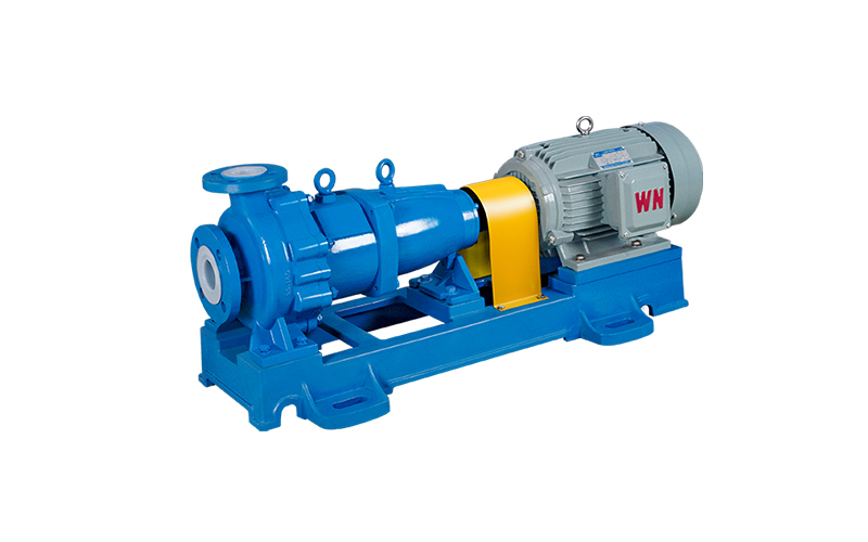
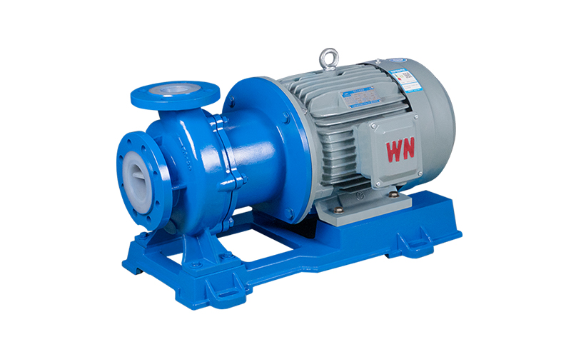
Pump and motor alignment skills
First, the importance of the pump
The rotation center of the two shafts connected by the coupling of the pump and the motor should be strictly concentric, and the coupling must be precisely aligned and centered when installed, otherwise it will cause great stress on the coupling, and will seriously affect the normal work of the shaft, bearings and other parts on the shaft, and even cause vibration or damage to the whole machine and the foundation.
Therefore, the search for the pump and motor coupling is one of the very important work links in the installation and maintenance process.
Second, the coupling to find the exact offset analysis
When installing a new pump, the verticality between the end face of the coupling and the axis can not be checked, but when installing the old pump, it must be carefully checked, and when it is not vertical, it is necessary to adjust the vertical and then find the right. In general, there are four situations that may be encountered.
1), S1=S2, a1=a2 The end face of the two half backrest wheels is in the correct position of both parallel and concentric, then the two axes must be located in a straight line.
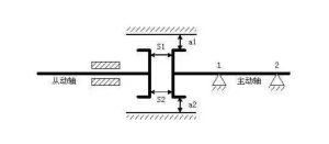
2), S1=S2, a1≠a2 The end faces of the two half backrest wheels are parallel but the axes are different, then there is a parallel radial displacement between the two axes e=(A2-A1)/2.
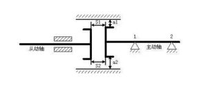
3), S1≠S2, a1=a2 Although the end faces of the two half backrest wheels are concentric but not parallel, there is an angular displacement α between the two axes.

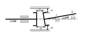
4), S1≠S2, a1≠a2 The end faces of the two half backrest wheels are both different centers and not parallel, and there is both radial displacement e and angular displacement α between the two axes.
The coupling in the first case is that we are looking for the ideal state that we need to strive to achieve, and the other three states are not correct, and we need to adjust it to achieve the first case.
When installing the equipment, first install the motor (that is, the pump head), so that its axis is in a horizontal position, and then install the drive (that is, the motor is often said), so the timing only needs to adjust the motor, that is, the method of adjusting the gasket at the foot of the motor to adjust.
Third, find the timing measurement adjustment method
The following mainly introduces two measurement adjustment methods commonly used in the maintenance process, which can be divided into different measurement tools:
1), the use of knife ruler and feeler ruler to measure the different heart of the coupling and the use of wedge gap rail or feeler ruler to measure the non-parallelism of the coupling end face, this method is suitable for elastic connection of low speed, precision requirements are not high equipment.
2), the use of dial indicator and table frame or special alignment tools (such as laser alignment calibration instrument) to measure the different hearts and non-parallel of the two couplings, this method is suitable for rotating equipment with high speed, rigid connection and high precision requirements.
Attention:
1), when using the feeler ruler and the knife ruler to find the timing, the surface of the radial end face of the coupling should be smooth, smooth, no rust, no burrs.
2), in order to see the light of the knife ruler, it is best to use a flashlight.
3) For the final measured value, the anchor bolt of the motor should be completely fastened without loosening.
4), use special tools to find the timing, make the same mark, in order to avoid the error of the measurement data, the backrest wheel should be divided into 4-8 points in order to obtain accurate data.
5), making records is an important part of finding the right.
When adding and adjusting the cushion surface, there are the following methods:
1), intuitive method (experience plus and minus cushion method). Because in the maintenance, some pump alignment does not fully have good conditions and tools, in the adjustment, the master’s experience will play a great role, each time add, reduce the pad should consider the tightness of the motor bolt and its margin.
2) Calculation method.
ⅰ. Original state
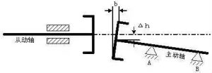
ⅱ. Elevate Δh
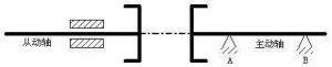
ⅲ. Adjusted axis line
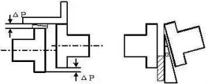
(1) First eliminate the height difference of the coupling
The motor shaft should be raised with A gasket to raise Δh, which is that the front support A and the rear support B should simultaneously pad Δh under the table.
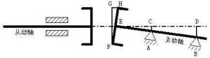
(2) Eliminate the opening of the coupling
Gaskets of different thickness are added under the A and B supports respectively, and the pad added to the B support should be higher than that of the A support.
Therefore, the total thickness of the adjusted gasket is: the front support A=Δh+AC; Rear support B=Δh+BD. (Among them, the calculation method of AC and BD can be thought about, how to obtain through measurable data.)