
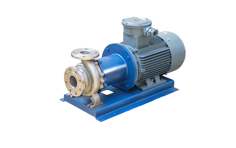
The magnetic pump consists of three parts: a pump, a magnetic transmission, and a motor. The key component, the magnetic transmission, consists of an outer magnetic rotor, an inner magnetic rotor, and a non-magnetic isolation sleeve. When the motor drives the outer magnetic rotor to rotate, the magnetic field can penetrate the air gap and non-magnetic materials, driving the inner magnetic rotor connected to the impeller to rotate synchronously, realizing contactless transmission of power and converting the dynamic seal into a static seal. Since the pump shaft and the inner magnetic rotor are completely enclosed by the pump body and the isolation sleeve, the “running, bubbling, dripping, and leaking” problem is completely solved, eliminating the safety hazard of flammable, explosive, toxic, and harmful media leaking through the pump seal in the oil refining and chemical industry, and effectively ensuring environmental protection, safe production and other needs.

1. Working principle and structural characteristics of magnetic pump
N pairs of magnets (n is an even number) are regularly arranged and assembled on the inner and outer magnetic rotors of the magnetic transmission, so that the magnetic parts form a complete coupled magnetic system. When the inner and outer magnetic poles are opposite to each other, that is, the displacement angle between the two magnetic poles is Φ = 0, the magnetic energy of the magnetic system is low; when the magnetic poles rotate to the same poles, that is, the displacement angle between the two magnetic poles is Φ = 2π/n, the magnetic energy of the magnetic system is large. After removing the external force, the magnetic poles of the magnetic system repel each other, and the magnetic force will restore the magnet to a state of low magnetic energy. Then the magnet moves and drives the magnetic rotor to rotate.
a. Internal and external magnetic steel
The permanent magnet made of rare earth permanent magnet material has a wide operating temperature range (-45-400℃), high coercivity, good anisotropy in the magnetic field direction, and no demagnetization will occur when the same poles are close to each other. It is a good magnetic field source.
b. Isolation sleeve
When a metal isolation sleeve is used, the isolation sleeve is in a sinusoidal alternating magnetic field, and eddy currents are induced on the cross section perpendicular to the direction of the magnetic field lines and converted into heat. The expression of eddy current is:. Among them, Pe-eddy current; K-constant; n-rated speed of the pump; T-magnetic transmission torque; F-pressure in the spacer; D-inner diameter of the spacer; -resistivity of the material; -tensile strength of the material. When the pump is designed, n and T are given by the working conditions. To reduce the eddy current, only F, D, etc. can be considered. The isolation sleeve is made of high resistivity and high strength non-metallic material F46, which is very effective in reducing eddy currents. The reinforcement sleeve is made of aerospace material PEEK (polyetheretherketone), with a high pressure resistance of 3Mpa, which is the best choice for conveying media with high specific gravity, such as 98 concentrated sulfuric acid and bromine.
c. Sliding bearings
The materials of the sliding bearings of magnetic pumps include impregnated graphite, filled polytetrafluoroethylene, engineering ceramics, etc. Since engineering ceramics have good heat resistance, corrosion resistance, and friction resistance, the sliding bearings of magnetic pumps are mostly made of engineering ceramics. Since engineering ceramics are very brittle and have a small expansion coefficient, the bearing clearance must not be too small to avoid shaft seizure accidents. Since the sliding bearings of magnetic pumps are lubricated with the medium being transported, different materials should be selected to make bearings according to different media and operating conditions.
d. Protection measures
When the driven parts of the magnetic transmission are running under overload or the rotor is stuck, the main and driven parts of the magnetic transmission will automatically slip off to protect the pump. At this time, the permanent magnets on the magnetic transmission will produce eddy loss and magnetic loss under the action of the alternating magnetic field of the active rotor, causing the temperature of the permanent magnets to rise and the magnetic transmission to slip and fail.
e. Control of cooling and lubricating liquid flow rate
When the pump is running, a small amount of liquid must be used to flush and cool the annular gap area between the inner magnetic rotor and the isolation sleeve and the friction pair of the sliding bearing. The flow rate of the coolant is usually 2%-3% of the pump design flow rate. The annular gap area between the inner magnetic rotor and the isolation sleeve generates high heat due to eddy currents. When the cooling and lubricating liquid is insufficient or the flushing hole is blocked, the medium temperature will be higher than the working temperature of the permanent magnet, causing the inner magnetic rotor to gradually lose its magnetism and the magnetic transmission to fail. When the medium is water or water-based liquid, the temperature rise in the annular gap area can be maintained at 3-5°C; when the medium is hydrocarbon or oil, the temperature rise in the annular gap area can be maintained at 5-8°C.
2. Material and selection
a. The pump generally uses corrosion-resistant, high-strength engineering plastics (F46). When the angle is greater than 90°, (imported Japanese Daikin PFA or American DuPont PFA), stainless steel, etc. are used as manufacturing materials. They have good corrosion resistance and can protect the transported medium from contamination. For example, the part of the CQB series magnetic pump that contacts the transported liquid is made of chemical-resistant fluoroplastic alloy. Fluoroplastic alloy is composed of ultra-high molecular weight polyperfluoroethylene propylene that can be thermoplasticized and one or more other plastics, and fillers can be added. For example, a plastic alloy composed of ultra-high molecular weight polyperfluoroethylene propylene and polytetrafluoroethylene, the former accounts for 0.1% to 99.9% by weight, and the latter accounts for 99.9% to 0.1% by weight. It is manufactured by a blending method of dry powder co-grinding or dry powder wet co-grinding. It is processed into various products by hot pressing or cold pressing sintering, which overcomes the cold flow and easy deformation of polytetrafluoroethylene and can extend its service life.
b. The bearings of the magnetic pump are immersed in the conveying medium and are lubricated and cooled by the conveying medium. The most commonly used bearings in China are graphite (ISC or SSIC). Graphite, especially impregnated graphite, has good self-lubrication, heat corrosion resistance, low friction coefficient, and a wide range of applications, but graphite is brittle and has low strength. It is very sensitive to shaft bending and local overload, so special attention should be paid. Three-layer composite bearings with steel as the matrix, porous bronze as the middle layer, and plastic as the surface layer have high compressive strength, low friction coefficient, stable size, and soundproofing and shock absorption, and have been used in recent years.
3. Advantages of magnetic pumps
Compared with centrifugal pumps using mechanical seals or packing seals, magnetic pumps have the following advantages.
a. The pump shaft is changed from a dynamic seal to a closed static seal, which completely avoids medium leakage.
b. No independent lubrication and cooling water are required, which reduces energy consumption.
c. The coupling drive is changed to synchronous drag, and there is no contact and friction. It has low power consumption, high efficiency, and damping and vibration reduction effects, which reduces the impact of motor vibration on the pump and the impact of cavitation vibration on the motor when the pump occurs.
d. When overloaded, the inner and outer magnetic rotors slip relative to each other, which has a protective effect on the motor and pump.
4. Precautions for operation
a. Prevent particles from entering
(1) Ferromagnetic impurities and particles are not allowed to enter the magnetic transmission device and bearing friction pair.
(2) After conveying media that are easy to crystallize or precipitate, flush it in time (fill the pump cavity with clean water after stopping the pump and drain it after running for 1 minute) to ensure the service life of the sliding bearing.
(3) When conveying media containing solid particles, filter it at the inlet of the pump flow pipe.
b. Prevent demagnetization
(1) The magnetic torque cannot be designed too small.
(2) It should be operated under the specified temperature conditions, and it is strictly forbidden to exceed the medium temperature. A platinum resistance temperature sensor can be installed on the outer surface of the magnetic pump isolation sleeve to detect the temperature rise in the annular gap area, so as to alarm or shut down when the temperature exceeds the limit.
c. Prevent dry friction
(1) It is strictly forbidden to run idly.
(2) It is strictly forbidden to evacuate the medium.
(3) When the outlet valve is closed, the pump should not run continuously for more than 2 minutes to prevent the magnetic transmission device from overheating and failure.
5. Operation procedures of magnetic pump
a. Pump start procedure: open the inlet valve before starting, fill the pump with the liquid to be transported; close the outlet valve; start the electric lift to check whether the pump is in the correct direction; after the pump starts, the outlet valve should be opened slowly, and after the pump reaches the normal operating state, adjust the outlet valve to the required opening. Test run for 5~10 minutes, if there is no abnormality, it can be put into operation.
b. Stop procedure: close the outlet valve; cut off the power supply; close the inlet. When the pump is not used for a long time, clean the flow channel in the pump and cut off the power supply.