
Introduce
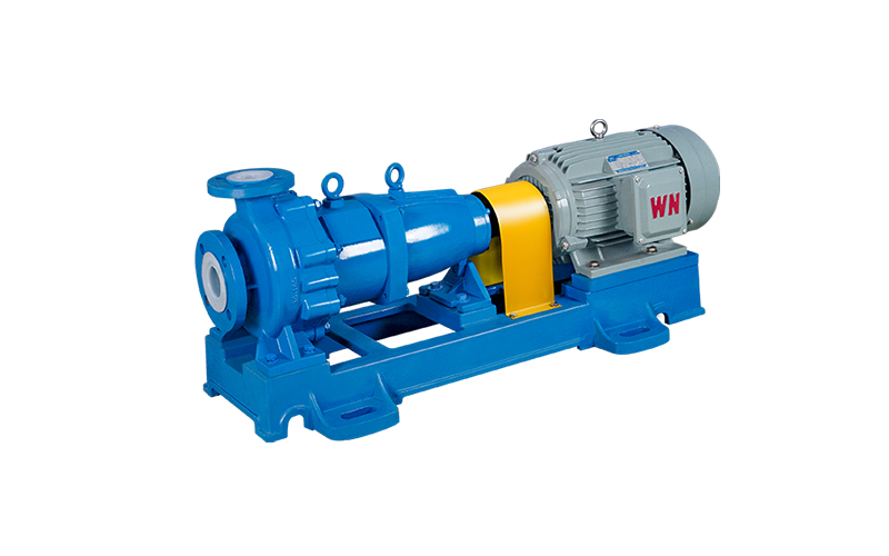
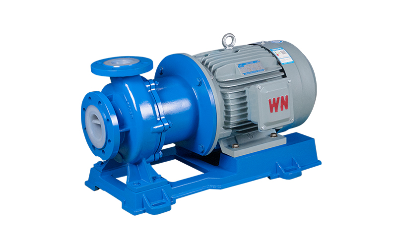
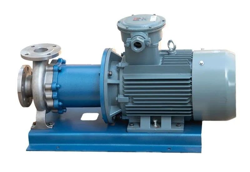
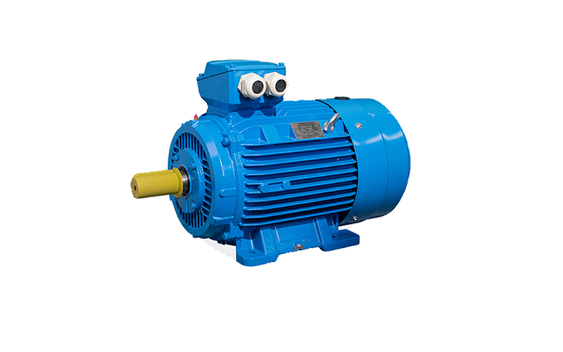
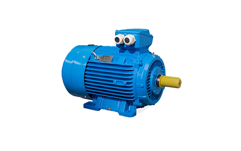
YE4 series explosion-proof low voltage three-phase asynchronous motor
Frame number: H63-55
Capacity: 0.12~450kW
Number of poles: 212P
Voltage: 1000v and below
enterprise mission
Committed to the scientific research and intelligent manufacturing of energy-saving motors, to become the leader of high-end manufacturing in the motor industry
The core of all work is to focus on “scientific and technological innovation”, “customer benefit maximization”, “green environmental protection”,
From product design, production and manufacturing process into the concept of green environmental protection,
Build the industry’s leading green brand with high energy saving, high environmental protection and high performance products.
corporate vision
Build a first-class high efficiency, energy saving and environmental protection motor professional production and research base, build a hundred years of enterprises, create an international brand, xing national industry.
Technology development direction: from high efficiency to super efficient development.
Product function development direction: motor to motor integration, systematization, intelligent development.
Adjust the marketing mode, go deep into the customer, and actively assist customers in the selection, design and installation of product solutions.
Instilling the concept of “green” from the source, customers will feel the long-term benefits brought by “green”, and promote the development of “green” large and medium-sized motors to create international brands.
core value
Integrity, collaboration, innovation, quality.
Integrity: abide by the law, integrity management. Cooperation: unity and cooperation, diversity and win-win. Innovation: break the stereotype, break the tradition. Quality: The pursuit of excellence, strive for first-class.
Answer to pump cavitation
What is cavitation?
When the local pressure of the liquid in the pump drops to the critical pressure, bubbles will be generated in the liquid. Cavitation is the entire process of bubble aggregation, movement, splitting, and elimination. The critical pressure is generally close to the vaporization pressure.
What are the hazards of cavitation?
1. Corrosion of overcurrent components
There are two reasons for corrosion:
Firstly, due to the high-frequency (600-25000Hz) impact generated by the bursting of bubbles, with a pressure of up to 49Mpa, mechanical erosion occurs on the metal surface;
The second reason is that during vaporization, heat is released, and there is a temperature difference battery that generates hydrolysis. The generated oxygen oxidizes the metal and causes chemical corrosion.
2. Pump performance degradation
When pump cavitation occurs, the energy exchange inside the impeller is disturbed and damaged, and its external characteristics are manifested by the Q-H curve, Q-P, and Q-eta curves decreasing. In severe cases, it can interrupt the liquid flow in the pump and prevent it from working.
For low specific speeds, due to the narrow and long flow channels between the blades, once cavitation occurs, bubbles fill the entire flow channel, and the performance curve will drop sharply.
For medium to high specific speeds, the flow path is short and wide, so there needs to be a transition process for bubbles to develop and fill the entire flow path. The corresponding performance curve starts with a slow decline, and then increases to a certain flow rate before sharply decreasing.
The most prone areas for cavitation in centrifugal pumps are:
At the front cover plate with the maximum curvature of the impeller, near the low-pressure side of the blade inlet edge;
Press out the low-pressure side near the inlet edge of the volute diaphragm and guide vanes in the chamber;
The sealing clearance between the outer circle of the blade tip and the shell of a high specific speed impeller without a front cover plate, as well as the low-pressure side of the blade tip;
The first stage impeller in a multi-stage pump.
Improve anti cavitation measures: Improve the structural design of the pump from the suction inlet to the vicinity of the impeller. Increase the overcurrent area; Increase the curvature radius of the inlet section of the impeller cover plate to reduce the rapid acceleration and pressure drop of the liquid flow; Appropriately reducing the thickness of the blade inlet and rounding the blade inlet to make it close to the streamline can also reduce the acceleration and pressure reduction around the blade head; Improve the surface smoothness of the impeller and blade inlet to reduce resistance loss; Extend the inlet edge of the blade towards the inlet of the impeller to allow the liquid flow to receive work in advance and increase pressure.
By using a pre induced wheel, the liquid flow performs work in advance in the pre induced wheel to increase the liquid flow pressure.
By using a double suction impeller, the liquid flow enters the impeller from both sides simultaneously, doubling the inlet cross-section and reducing the inlet flow rate by one.
The design condition adopts a slightly larger positive angle of attack to increase the blade inlet angle, reduce the bending at the blade inlet, reduce blade blockage, and increase the inlet area; Improve working conditions under high flow rates to reduce flow losses. But the positive angle of attack should not be too large, otherwise it will affect efficiency.
Using anti cavitation materials. Practice has shown that the higher the strength, hardness, and toughness of materials, the better their chemical stability, and the stronger their resistance to cavitation.
Measures to increase the effective cavitation margin of the liquid inlet device: Increase the pressure of the liquid level in the storage tank in front of the pump to increase the effective cavitation margin.
Reduce the installation height of the suction device pump.
Change the suction device to a backflow device.
Reduce the flow loss in the pipeline before the pump. Try to shorten the pipeline within the required range, reduce the flow rate in the pipeline, reduce bends and valves, and increase valve opening as much as possible.
Reduce the temperature of the working medium at the pump inlet (when the transported working medium approaches saturation temperature).
The above measures can be comprehensively analyzed and applied appropriately based on the selection of pump types, materials, and on-site usage conditions.
Cavitation margin and suction head: When the pump is operating, the liquid at the inlet of the impeller will generate vapor under a certain vacuum pressure. The vaporized bubbles will cause erosion on the metal surface of the impeller under the impact motion of the liquid particles, thereby damaging the impeller and other metals. At this time, the vacuum pressure is called vaporization pressure. Cavitation margin refers to the excess energy per unit weight of liquid at the pump inlet that exceeds the vaporization pressure, expressed in meters and expressed in (NPSH) r.
The suction head is the necessary cavitation margin Δ h, which is the vacuum degree that the pump is allowed to suction liquid, that is, the installation height allowed by the pump, in meters. Suction lift=standard atmospheric pressure (10.33 meters) – NPSH – safety margin (0.5 meters) – standard atmospheric pressure can pressure the vacuum height of the pipeline to 10.33 meters.
For example, if the cavitation margin of a certain pump is 4.0 meters, calculate the suction head Δ h
Solution: Δ h=10.33-4.0-0.5=5.83 meters
Each unit of measurement and its corresponding letter: NPSH refers to the difference between the total head of the liquid at the pump inlet and the pressure head at which the liquid vaporizes. The unit is marked in meters (water column) and expressed in (NPSH), which can be divided into the following categories: NPSHa – device NPSH, also known as effective NPSH, which is less prone to cavitation as it increases;
NPSHr – Pump NPSH, also known as necessary NPSH or pump inlet dynamic pressure drop, the smaller the NPSHr, the better the anti cavitation performance;
NPSHc – critical cavitation margin, refers to the cavitation margin corresponding to a certain decrease in pump performance;
[NPSH] – allowable cavitation margin, which is the cavitation margin used to determine the operating conditions of the pump, usually taken as [NPSH]=(1.1-1.5) NPSHc.