
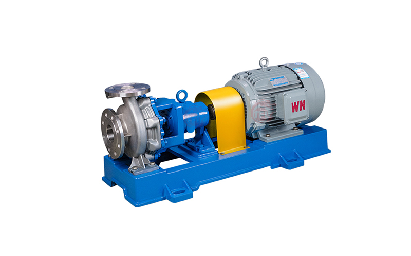
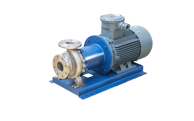
Chemical centrifugal pumps are commonly used chemical water pumps in industrial production. A typical chemical centrifugal pump consists of main components such as a pump casing, impeller, mechanical seal, bearing, and coupling. Additionally, components like sealing rings and wear rings should not be overlooked. Below is a detailed overview of the assembly requirements for each component of a chemical centrifugal pump and the specific assembly procedures.
Assembly Requirements
1. Cleaning
- All parts must pass inspection, with material codes complying with drawing requirements. Their surfaces should be thoroughly cleaned, and mating surfaces should be coated with machine oil.
- The interior of the bearing housing must be cleaned and painted with oil-resistant enamel. Allow it to dry naturally for 24 hours, and only proceed with assembly after passing inspection.
2. Requirements for Sub-assembly and Final Assembly
- When assembling flat keys and bearings, do not strike them directly with a hammer. Instead, use a wooden hammer, copper rod, or specialized assembly tools.
- For interference fits (e.g., bearing inner rings with tolerances r6 or s6), heat the bearing to 80-120°C for hot assembly.
- Apply dry oil to the end of the stud bolt that connects to the base. Ensure all stud bolts have the same length and are tightened evenly.
- During assembly, avoid scratching the surfaces of parts—especially mating and sealing surfaces—as this may affect assembly quality.
3. Assembly of Bearings and Shaft
- Heat the bearing to 90°C-110°C in a heating furnace, then mount it on the shaft and allow it to cool.
- First, install the left bearing cover of the bearing housing. Then, insert the assembly of the bearing and shaft into the bearing housing, positioning it against the left bearing cover.
- Measure the gap between the drive-end bearing cover and the end face of the bearing outer ring:
- For CZ pumps: 0.30-0.70 mm
- For ZA pumps: 0-0.42 mm
- If paired bearings are used for ZA pumps, use a lock nut to secure the bearings until the outer rings of the two bearings can rotate slightly relative to each other—this ensures optimal internal clearance.
4. Assembly of Wear Rings with Impellers and Pump Bodies
- When assembling wear rings with impellers and pump bodies, ensure the wear ring is evenly installed into the impeller or pump body around its circumference to minimize geometric deviations of the wear ring.
- After installing set screws or completing welding, measure the radial runout of the impeller and wear ring, as well as the gap between them. The measured values must comply with the general technical specifications for pump assembly. Refurbish any parts that exceed the tolerance range.
5. Impeller Installation
For Single-stage Pumps
- Conduct a static balance test on the impeller to meet technical requirements.
- Mount the impeller on the shaft, secure it with a nut, then insert the entire rotor into the pump body and tighten with a nut.
For Multi-stage Pumps
- In addition to a static balance test for each impeller, perform a trial assembly of rotor components: assemble all impellers with the shaft, mark their positions, and conduct a dynamic balance test (results must meet technical requirements).
- During installation:
- Push the balance drum, shaft sleeve, and all impellers to the right until the first-stage impeller and shaft sleeve rest against the shaft shoulders respectively.
- Measure the gap between the shaft sleeve and the balance drum—ensure it is ≥ 0.5 mm. If the gap is too small, refurbish the balance drum to meet the requirement.
- Insert the shaft with the first-stage impeller into the suction casing, then install impellers and middle casings with guide vanes onto the shaft step-by-step until reaching the discharge casing.
- Secure the pump components with bolts, then install the balance device, seals, and bearing components.
- Confirm the correct mid-position of the rotor and adjust the axial clearance of the tapered bearings to 0.04-0.06 mm.
6. Mechanical Seal Assembly
-
Ensure all mating surfaces fit tightly during assembly, and apply industrial petroleum jelly lubricant to the friction surfaces.
-
Installation of Cartridge Mechanical Seals
- First, use stud bolts and nuts to mount the seal onto the pump cover.
- After inserting the pump shaft into the seal sleeve and connecting the bearing housing to the pump body, remove the stop washer of the seal from the shaft sleeve.
- To reduce wear on O-rings, apply lubricant to the areas where O-rings pass. For EPDM (ethylene-propylene-diene monomer) O-rings, use soapy water or water as lubricant.
-
Installation of Packing Seals
- Before installation, determine the length of each packing ring based on the outer diameter of the shaft sleeve. Slightly flatten the ring, wrap it around the shaft sleeve, and push it into the stuffing box. If a water seal ring is used, install it as required.
- After installing all packing, evenly tighten the packing gland.
7. Adjustment of Bearing Housing for Horizontal Multi-stage Pumps
- For bearing housings of multi-stage pumps that are not positioned via spigots, perform alignment adjustment during installation:
- Rotate the adjustment bolts to move the bearing housing vertically and horizontally.
- Measure the extreme positions of the bearing housing in both directions and take the average value.
- Lock the adjustment bolts with lock nuts, install locating pins, then assemble the seal and bearings. Finally, adjust the axial alignment of the rotor.
8. Coupling Installation (Pump Head Fixed)
-
Apply lubricant to the inner hole, shaft journal, and key of the coupling during assembly. Apply force evenly to avoid impact damage to parts.
-
Installation of Jaw Couplings
- Similar to diaphragm couplings: mount the two flanges of the jaw coupling onto the corresponding shafts respectively, and adjust their relative positions using a straightedge.
- If the rotational speed is ≥ 3600 rpm, use the alignment method for diaphragm couplings.
-
Installation of Diaphragm Couplings
- Mount the pump-end and motor-end couplings onto their respective shafts.
- Use a dial indicator to align the coaxiality of the two shafts (adjust the motor position with shims in the vertical direction):
- Radial runout ≤ 0.1 mm, end runout ≤ 0.05 mm (for general conditions).
- If rotational speed > 3600 rpm: radial runout ≤ 0.05 mm, end runout ≤ 0.03 mm.
- After meeting the requirements, install the intermediate coupling section.
- If the operating temperature is relatively high (approximately > 130°C), perform alignment correction under the high-temperature conditions when the pump is in operation.
9. Painting
- Painting should be carried out in a clean, dry area with an ambient temperature of not less than 5°C and relative humidity not exceeding 70%. If relative humidity exceeds 70%, add an appropriate amount of moisture-proof agent to the paint to prevent the coating from turning white.
- Do not paint the following areas:
- Non-ferrous metal parts, stainless steel parts, and parts plated with chrome, nickel, cadmium, silver, tin, etc.
- Sliding parts, mating parts, sealing surfaces, thread surfaces.
- Nameplates and direction plates.
