
Įvadas:
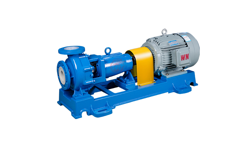
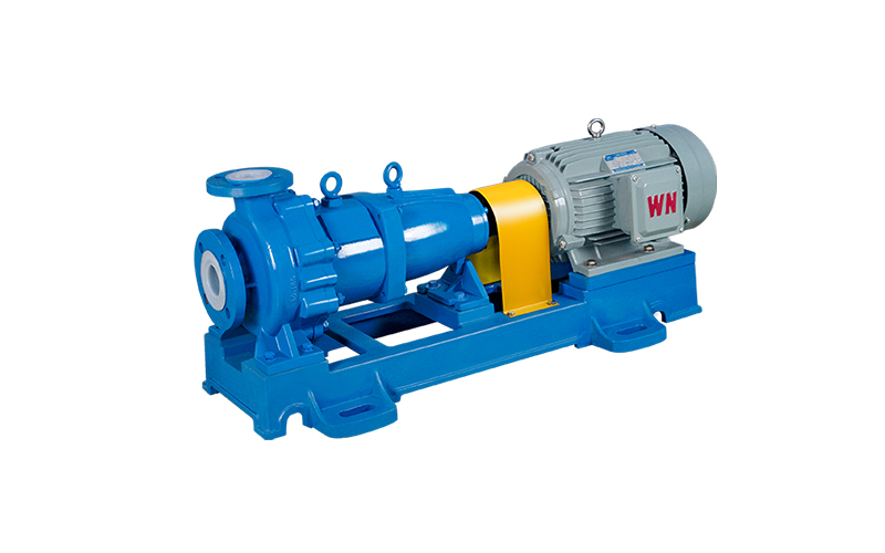
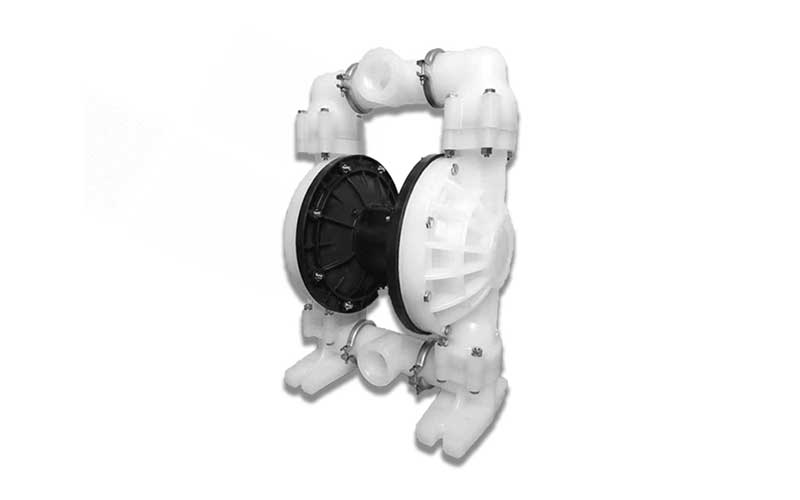
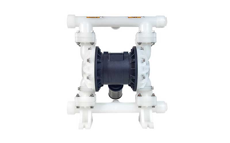
1. Pneumatic diaphragm pump is a new type of conveying machinery, using compressed air as the power source, the volume change caused by the reciprocating deformation of the diaphragm pump, for all kinds of corrosive liquids, liquids with particles, high viscosity, volatile, flammable, highly toxic liquids, can be pumped out.
2. The pneumatic diaphragm pump has four materials: engineering plastics, aluminum alloy, stainless steel, cast iron. Pneumatic diaphragm pump according to different liquid media respectively using nitrile rubber, neoprene rubber, fluorine rubber, polytetrafluoroethylene, polytetrafluoroethylene, etc., to meet the needs of different users. Placed in a variety of special occasions, used to pump a variety of conventional pump can not pump the medium, have achieved satisfactory results.
Suitable for adhesives and glues, all kinds of tiles, porcelain, pottery glaze, all kinds of abrasives, etchant, oil and mud. It can transport particles up to 10mm in diameter, and has little wear to the pump when pumping mud and impurities. No need for irrigation, suction up to 7m, lift up to 50m. Through good performance, it can transport some medium that is not easy to flow, and has many advantages of self-priming pump, submersible pump, shield pump, mud pump and impurity pump.

Selection steps:
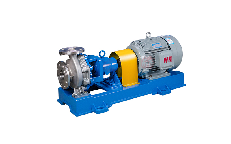
Relatively speaking, pipeline pumps do not have high requirements for flow rate and the medium being transported, so the selection of pipeline pumps mainly considers the appropriate flow rate and head. The selection criteria for pipeline pumps should be based on the process flow, water supply and drainage, and be considered from five aspects, including liquid conveying capacity, disassembly head, liquid nature, pipeline arrangement, and control of operating conditions.
We mainly consider five aspects, including liquid conveying capacity, device head, liquid properties, pipeline layout, and operating conditions.
1、 First, list the basic data:
1. Characteristics of the medium: medium name, specific gravity, viscosity, corrosiveness, toxicity, etc.
2. What is the particle diameter and content of the solid contained in the medium.
3. Medium temperature: (℃)
4. The required flow rate for industrial pumps can generally ignore the leakage rate in the pipeline system in the process flow, but the impact of process changes on flow rate must be considered. If agricultural pumps use open channels for water transportation, leakage and evaporation must also be considered.
5. Pressure: suction pool pressure, drainage pool pressure, pressure difference (head loss) in the pipeline system.
6. Pipeline system data (diameter, length, type and number of pipeline accessories, geometric elevation from suction tank to pressure tank).
If necessary, a device characteristic curve should also be made.
Secondly, when designing and arranging pipelines, the following precautions should be taken:
A、 Reasonable selection of pipeline diameter. With a larger pipeline diameter, at the same flow rate and lower liquid flow velocity, the resistance loss is small. However, with a higher price and smaller pipeline diameter, the resistance loss will increase sharply, leading to an increase in the head of the selected pump, an increase in belt power, and an increase in both cost and operating expenses. Therefore, a comprehensive consideration should be given from both technical and economic perspectives.
B、 Discharge pipe and its fittings
The maximum pressure that can be withstood should be considered.
C、 The pipeline layout should be arranged as straight as possible, minimizing the number of accessories in the pipeline and minimizing the length of the pipeline. When turning is necessary, the bending radius of the elbow should be 3-5 times the diameter of the pipeline, and the angle should be greater than 90 ℃ as much as possible.
D、 The discharge side of the pump must be equipped with valves (ball valves or shut-off valves, etc.) and check valves. Valves are used to adjust the operating point of the pump, and check valves can prevent the pump from reversing when the liquid flows back, and prevent the pump from being hit by water hammer. (When the liquid flows back, a huge reverse pressure is generated, causing pump damage)
2、 Determine the flow rate and head of the pipeline pump, and determine the flow rate
Flow rate is one of the important functional data for pipeline pump selection, which directly relates to the production and transportation capabilities of all devices. In the hypothetical process of the hypothetical hospital, three flow rates of the pump can be calculated: normal, minimum, and maximum. When deciding the pump, the maximum flow rate should be taken as the basis, taking into account the abnormal flow rate. When the maximum flow rate is not reached, 11 times the abnormal flow rate can be taken as the maximum flow rate.
a、 If the minimum, normal, and maximum flow rates have been given in the production process, the maximum flow rate should be considered.
b、 If only normal flow rate is provided in the production process, a certain margin should be considered.
For large flow and low head pumps with ns>100, a flow margin of 5% should be taken. For small flow and high head pumps with ns<50, a flow margin of 10% should be taken. For pumps with ns ≤ 50, a flow margin of 5% should also be taken. For pumps with poor quality and poor operating conditions, a flow margin of 10% should be taken.
c、 If the basic data only provides weight flow rate, it should be converted to volumetric flow rate.
3、 The head required for dismantling the system is another important performance data for pipeline pump selection, and for some cases, the head needs to be increased by 5-10% margin for selection.

FAQ:
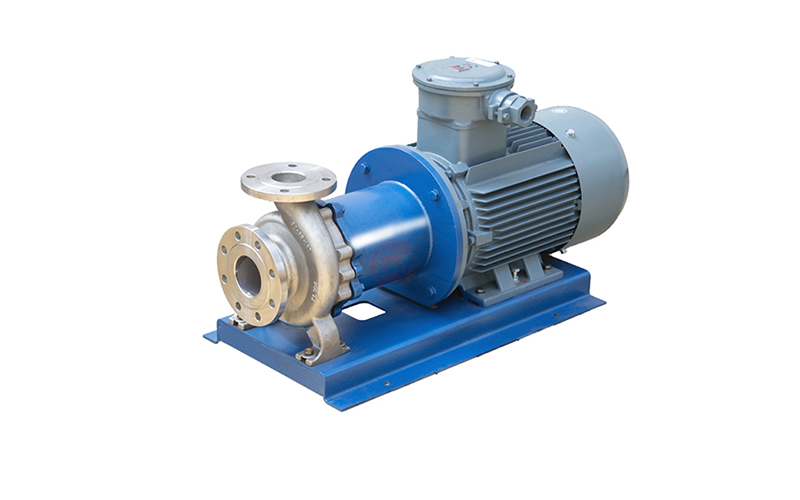
Q:How long can magnetic driven centrifugal pump dry run?
A:Anyone familiar with industrial magnetically driven pumps is asked questions about pump dry operation. After all, home dishwashers and washing machines do it all the time. Some bearing materials can do that, right? That’s a qualified “yes,” of course, but it’s time to take a closer look at the dry run.
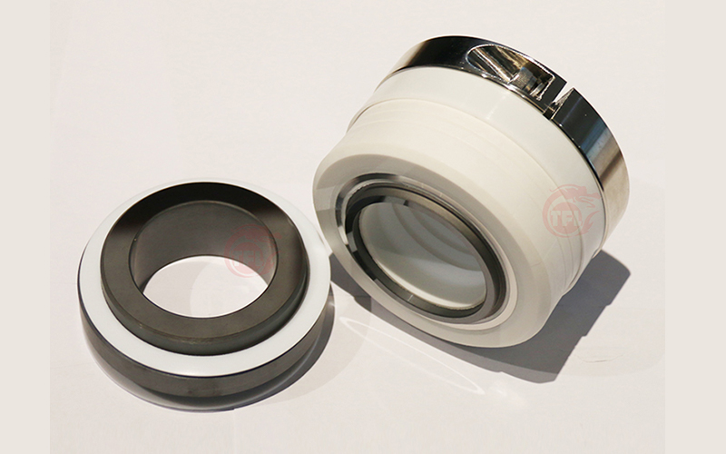
In all but literal terms, “dry run” is a misnomer. Industrial pumps are mechanically sealed or unsealed and may be subject to what is known in the industry as “dry running.” This article will focus on a magnetically driven pump configuration with a silicon carbide (SiC) bearing assembly, one of two types of rotary power centrifugal pumps that are not sealed.
Magnetically driven pumps have product-lubricated bearings that require liquid to function properly. These hydrodynamic (sliding) bearings rely on a fluid barrier separating the bearing assembly, which becomes wedge-shaped when there is relative motion between the two surfaces. When this fluid barrier is breached, the two surfaces will come into contact and may cause damage to the component. This effect can be cumulative, leading to component failure when the limit is reached.
If the SiC surface touches during operation, the component may rupture in a short period of time (depending on several factors). This does not mean that the pump stops running immediately. The broken SiC block can still support the shaft well enough to allow the pump rotor to rotate. Broken SiC can be detected by increased vibration and increased power. If we keep running, the pump will only get worse.
When the pump loses suction, it should be stopped immediately. Damage to a silicon carbide component can occur within seconds. This is determined by using a power monitor to detect when the motor load suddenly changes to protect the main components of the pump. Continued operation without sufficient liquid at the suction inlet can quickly lead to serious damage to the SiC component.
In order to extend service life, the pump only needs to have available liquid, operate within the flow curve of the pump, and be within the design limits of the pump. Note that it is best to start the pump when the pump outlet valve is partially open (about a quarter open); The inlet valve should always be fully open when the pump is running and should only be closed when the pump must be isolated for maintenance reasons.
The SiC bearing material cannot withstand mechanical impact, and when the lubrication between the surfaces of the bearing components is insufficient, mechanical impact will occur, resulting in contact between the components. During the operation of the system, there are several conditions that will produce this situation.
The following are considered system anomalies, during which the bearing lubrication film barrier is damaged:
1) The pump runs with the valve closed
2) Insufficient pump suction pressure [insufficient available net positive suction head (NPSHa)] leads to cavitation
3) Run for a long time under very low flow conditions
4) Long time operation under high flow conditions – “off the curve” or beyond the maximum flow range
5) Excessive circulation of system traffic from one flow to another
6) Too high a temperature causes the pumping fluid (lubricating flow) to vaporize on the surface of the bearing component – or there is not enough internal system pressure to maintain the liquid state while the pumping fluid passes through the pump
7) Start the motor when there is no liquid in the pump, including a short start when checking the direction of rotation
8) The inlet of the impeller blade is blocked
Many suppliers offer specially treated sintered SiC to provide enhanced dry run capability in the event of a system failure. Some manufacturers use a coating that adheres to the substrate SiC, while others use a dip method where the coating is mechanically integrated into the substrate. All of these are known in the industry as diamond-like coatings (DLC). These treatments significantly reduce the coefficient of surface friction compared to standard sintered SiC. Under system anomalies and other dry operating conditions, less friction and less heat are generated, reducing the possibility of damage to bearing components due to mechanical contact or thermal shock.
Regarding pumping equipment and product lubrication bearings, no one recommends that the pump run without liquid passing through. When the unit suction is missing, some liquid will remain inside the bearing part, but as the operation continues, these liquids will soon be pressed out of the side of the bearing part. The vaporization of the liquid can occur very quickly, depending on the size (specification) of the pump.
Determining dry run time requires specific testing of pump specifications and associated operating conditions. For small pumps up to 2 hp, tests have shown that the dry run time is a few minutes; For the smallest pumps with DLC-coated bearings, the dry run time can be extended to more than an hour. The greater the input power of the pump, the shorter the time before the bearing system is damaged. For large pumps over 50 hp, while the DLC coating is still helpful, the time before damage occurs is still short. In the absence of DLC-coated bearings or without liquid in the pump, electrifying the motor to check the direction of rotation of the pump may cause some bearing damage. Dry run damage initially appears as a cracked or chipped SiC component. When the liquid disappears and the rotating ceramic part comes into contact with the stationary part, the SiC breaks, breaking into small pieces. Continuous operation can damage more pump parts, such as the shaft, rear housing, housing cover and impeller – all of which are expensive parts. This type of pump damage is preventable.
Again, it is recommended that the pump be protected by a power monitor and that the low power trip point be set as the first indicator representing a loss of suction. Setting a low power trip point time delay of 2 to 3 seconds prevents the pump from tripping when large bubble steam/air is discharged through the pump and there is a brief loss of suction. Trying to run longer to empty the suction line of the product will result in damage to the pump, which is more expensive than the small amount of product that may be left in the suction line. A properly set power monitor will save pump owners money.
Lined magnetic drive pumps use SiC or non-metallic bearing materials. Some of the latter may have enhanced lubricity, but are still constrained by impaired lubrication operation.
Shielded electric pumps are another type of non-sealed centrifugal pumps that typically use softer bearing materials, including carbon, which is more lubricated but easily worn. This requires a bearing monitoring system to avoid component damage.
For mechanically sealed pumps, the sealing surface operates on a similar hydrodynamic film and requires the same type of lubrication. Nor do they survive long periods of dry operation without damage.
Most damage to magnetically driven pumps can be avoided. The best answer to this headline question is not to let the pump run dry.
