
I. Analysis of the Component Structure of Chemical Corrosion-Resistant Magnetic Pumps
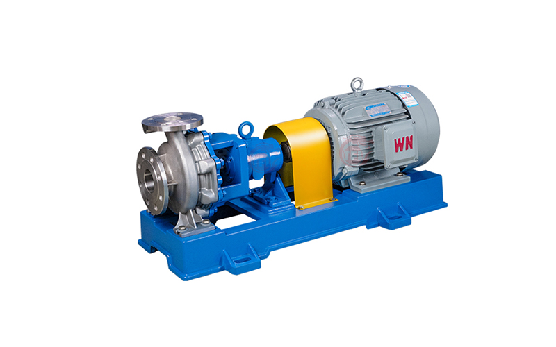
Structure and Components of Magnetic Pumps: A magnetic pump consists of three main parts: the pump itself, the magnetic drive, and the electric motor. The magnetic drive, in turn, is composed of an outer magnetic rotor (outer magnet assembly), an inner magnetic rotor (inner magnet assembly), and a non-magnetic containment shell (isolating sleeve).
The structure of fluoroplastic magnetic pumps and stainless steel magnetic pumps is quite similar. The key difference lies in how long the magnetic blocks retain their magnetic properties.
Currently, there are many magnetic materials available for magnetic pumps. The most commonly used are ALNICO (Alnico), ferrites, and rare-earth permanent magnets such as SmCo5 (samarium-cobalt, conventional designation 1:5), Sm(Co, Cu, Fe, Zr)7.4 (conventional designation 2:17), and NdFeB (neodymium-iron-boron). Rare-earth permanent magnets are preferred. The most powerful is neodymium magnet NdFeB, which has a high energy product (up to 28×10^4 T·A/m) and an intrinsic coercive force exceeding 1120 kA/m, making it highly popular. However, its operating temperature should not exceed 120°C. For high-temperature conditions, samarium-cobalt magnets can be chosen, for example, Sm(Co, Cu, Fe, Zr)7.4 with an energy product of about 192×10^3 T·A/m, which can operate at temperatures up to 300°C.
II. Detailed Structure of Common Types of Magnetic Pumps on the Market:
- Casing Section: Consists of the pump casing and the casing cover, which withstand the full operating pressure of the pump. The hydraulic design of the impeller complies with the API 685 standard and is a key component characterizing the hydraulic performance of the pump. Its function is to force the liquid to rotate, thereby converting the mechanical energy of the driver into liquid energy.
- Inner and Outer Rotors (Magnetic Rotors): Used together, they form the magnetic drive of the pump.
- Containment Shell (Isolating Sleeve): This is the component that fully realizes the main advantage of magnetic pumps – absolute leak-tightness.
- Rotor Assembly: Divided into rotating parts mounted on the pump shaft and rotating parts mounted on the drive shaft.
- The Pump Shaft is a critical component that carries the impeller and the inner magnetic rotor, and transmits torque.
- Rotating parts on the Pump Shaft (impeller, bearings, thrust ring components, inner magnetic rotor assembly, and the pump shaft itself) form the part of the rotor in contact with the pumped medium.
- Rotating parts on the Drive Shaft (outer magnetic rotor assembly, rolling bearings, drive shaft sleeve, and the drive shaft itself) form the part of the rotor exposed to air.
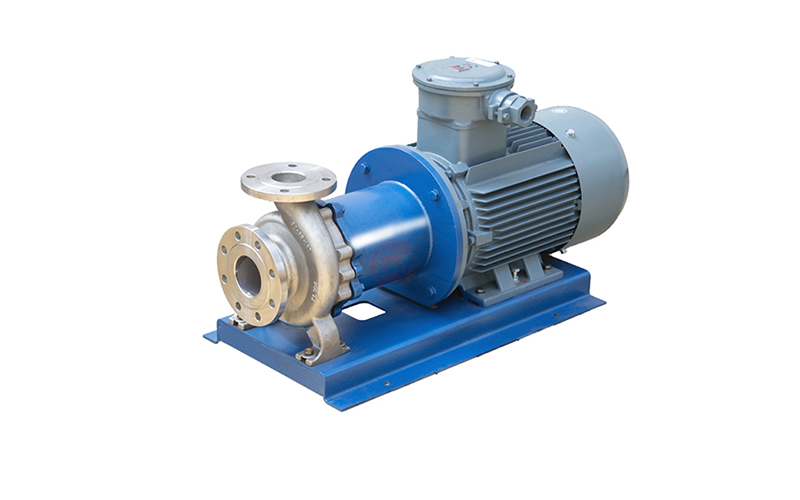
- Drive Section: The pump is connected to the driver using an extended diaphragm coupling. For maintenance, it is sufficient to remove the center diaphragm of the coupling.
- Connection Section: Consists of the connection frame and bearing housing – these are stationary components providing connection and support functions.
- Sleeve Bearings, Shaft Sleeves, and Thrust Discs: These are components that support and locate the elements of the pump rotor assembly.
The magnetic coupling of the pump is integrated with the pump casing, making the design compact, easy to maintain, safe, and energy-efficient. The magnetic coupling also provides overload protection for the drive motor. Since the pump shaft contacts the medium, its material must be corrosion-resistant, have high machining precision, high strength, or be heat-treated to increase strength.
III. Magnetic Pump Fault Analysis and Troubleshooting
The main advantage of magnetic pumps is the absence of leaks, completely solving the problem of “leaks, spills, drips, and seepage.” However, magnetic pumps also have corresponding disadvantages:
- High alignment requirements. If the pumped medium contains contaminants, accelerated wear of the inner magnetic rotor and the containment shell can occur.
- High requirements for the material used to manufacture the containment shell.
- The efficiency of magnetic pumps is generally lower than that of conventional centrifugal pumps. Dry running (operation without the pumped medium) is strictly prohibited.
- Application limitations: Magnetic pumps have specific requirements regarding ambient temperature, motor temperature, working pressure, as well as the density and solid particle content of the pumped medium.
- Relatively high cost.
IV. Precautions for Using Magnetic Pumps:
- After installation, manually rotate the coupling to check for any binding or friction. To prevent contaminants from entering the pump, a filter should be installed at the pump inlet with a filtration area 3-4 times larger than the cross-sectional area of the pipeline.
- Dry running (operation without medium) is strictly prohibited. For pumps with high head, a check valve should be installed on the discharge pipeline to prevent damage from water hammer during sudden shutdown.
- Pump Start-up Procedure: Before starting, open the suction valve and completely fill the pump with the liquid to be pumped. Close the discharge valve. Jog the electric motor to check the correct direction of rotation of the pump. After starting the pump, open the discharge valve slowly. After the pump reaches normal operating conditions, adjust the discharge valve to the required opening. Perform a test run for 5-10 minutes. If no abnormalities are found, the pump can be put into operation.
- Pump Shutdown Procedure: Close the discharge valve. Cut off the power supply. Close the suction valve. For prolonged shutdowns, flush the pump’s flow passages and disconnect the power supply.
